Anatomy of a PID Loop
A high level, block diagram view of a closed loop feedback control system in the form of a PID Loop is shown below.
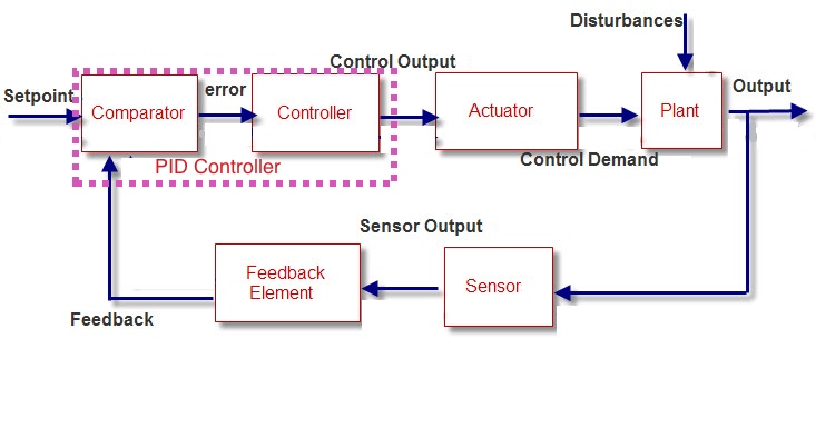
One element that is missing from this diagram is any signal conditioning elements, such as noise filters or signal amplifiers. These have been left out for simplification. But be warned: Filters Can Seriously damage your control strategy’s health. See the PID Tuning blueprint for a detailed discussion on the dangers of filtering.
Let’s go through each element of this closed loop PID control system:
Setpoint: The setpoint is the signal that tells the control system what the user wants as his desired output. Also known as command inputs, reference signals and inputs.
Output: Those physical characteristic of the plant which you want to control.
Comparator: Simply a subtraction block. Subtracts the feedback from the setpoint to get the error.
Controller: This baby processes the errors using a PID Algorithm to produce a corresponding Control Output that will ultimately cause the plant to behave in a desired way. (Assuming you have got the PID Controller Tuning right!)
Note: The Comparator and the Controller make up the PID Controller
Control Output: This instructs the actuators how much to adjust to manipulate the process to get the desired output.
Actuator: Translates the control output into physical changes in the plant’s behaviour. Essentially it supplies energy of some form to the plant to modify its behaviour.
Control Demand: This is the physical action which supplies the energy to change the processes' behaviour
Plant: The process or entity to be controlled.
Sensor: Measures the physical characteristics of the plant and produces a corresponding signal that represents that characteristic.
Feedback Element: The feedback element modifies the sensor signal in order to improve the final control of the plant.
Feedback: The signal produced by the feedback element which is used to construct the errors.
Disturbances: External Influences acting on the plant.
The PID loop shown can have any number of inputs and outputs. I’ve just shown 1 for simplicity. One thing that can make these systems a real bitch if therwe is more that one group of signals is that an input on only one channel will produce an output on all channels. This effect is called interaction.
Luckily for us, in many real-world systems the interaction is very small and therefore each channel, or loop of the control system can be treated separately.