By Finn Peacock, Chartered Electrical Engineer and Founder of PIDtuning.net
Mistake #1
Thinking all processes are tuned the same way
Please do not to fall into the trap of thinking that there is a 'one size fits all' approach to tuning PID loops whether you have a pressure, temperature, servo, pH or any other type of control loop.
There are actually 2 distinct types of processes:
* Integrating Processes and
* Self-Regulating Processes
You need to follow a very different set of tuning rules for each type.
You have to beware of tuning methods that don't make this distinction. For example: the famous Ziegler Nichols technique that I love to hate :-)
Look, I could fill the rest of this page with a rant about the damage that Mr Ziegler and Mr Nichols have inflicted on the control systems of the world, but instead I'll take a long, deep breath and opt for the good karma option…
This will walk you through the difference between an Integrating and Self Regulating process, and show you how to identify which flavor *your* process is.
This is a vitally important step as you have to use very different tuning methods depending on whether your process is self-regulating or integrating.
Read the following and take 10 minutes to identify YOUR process type, because tuning your process without knowing which tuning technique to apply is like pulling up to the gas station and not knowing if you should fill up with diesel or unleaded.
Step 1: Identify your process type.
The absolute first thing that we need to do is: Understand the type of process that we are looking at.
The type of process is defined by its dynamic characteristics. Which - to put it in plain English - means:
“What general shape do we see on a trace of the process variable (PV) when we put the process into manual mode and step the process input with the Manipulated Variable (MV)”
Manual Control:
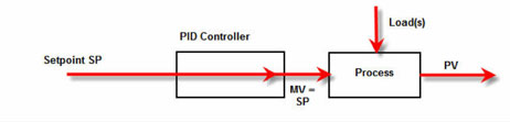
"Putting the process into manual" means switching the controller into manual. The effect of this is that we remove the feedback from the process and the controller simply sets its output, the MV, to the value of the controller’s only input, the SetPoint (SP).
The block diagram looks like this:
Figure 3- Manual Control AKA Open Loop Control
When a controller is in manual then we say that the process is in OPEN LOOP control.
If you step the MV of a process in open loop (by stepping the SP – remember in open loop the SP=MV) and watch the PV on a trend, for approximately 98% of processes, the line that is drawn on the screen will be one of two shapes depending on whether the process is:
Self-Regulating
Or
Integrating (sometimes called …. Non-self-regulating)
A critical part of tuning a PID loop is first identifying which of these 2 process types you have. I have never found a widely published PID tuning technique that differentiates between the two – one of the reasons that they perform so badly.
We will be using different tuning techniques - depending on the process type - so don't be tempted to skip this step!
Runaway Processes
A small minority of processes are neither self-regulating nor integrating and, rather unhelpfully, are unstable under open loop control. That is, if you switch the controller to manual, the PV will continue to rise (or fall), possibly in an exponential fashion, until some physical, possibly disastrous, limit is reached. These are called runaway processes. The most common of these processes is the exothermic reactor with cooling jacket. As the temperature rises, the reaction rate increases, causing additional heat to be generated, increasing the rate of change of the temperature. This process is only kept stable through controlling the flow of cooling water to its jacket. These types of processes need special rules to tune, because they may go unstable if the gain is too high OR TOO LOW. Each runaway process will be very different, so tuning rules for these rare processes are not covered by this blueprint.
How to identify your process:
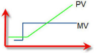
If you step your MV in open loop and this causes the PV to start rising/falling and it keeps moving in that direction in a mostly linear fashion - your process is an integrating process.
Figure 4 - Dynamic Response of an Integrating process
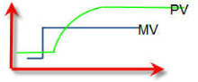
If you step your MV in open loop and this causes the PV to start rising/falling, but the gradient quickly starts to decrease until it has leveled off to flat, then you have a self regulating process.
Figure 5 - Dynamic Response of a Self Regulating Process
Think about what your process will do when stepped in open loop, and if you are not sure try an open loop step test by following the procedure below:
Be Aware: If your process is an integrating process, the step input will cause the output to rise (or fall) and keep on moving up or down until you step the MV back down. Because of actuator hysteresis, you may have to move the MV to a value that is below where you started before the PV completely levels off.
Procedure to determine process type:
Place the controller in manual.
In manual the Controller output (MV) will exactly follow the setpoint (SP).
Talk to the process operators and determine how much you can step the SP without causing production problems.
Step the controller setpoint 3-5% and watch the response.
Look for a self regulating, or a integrating response on the PV
If it is an integrating response and you want to stop the PV rising, first step the SP back to its original value, then reduce it in 1% steps until the PV flattens out. A self regulating process will, of course, flatten out on its own.
Mistake #2
Tuning your loop in Closed Loop
If you have been struggling to tune your loop it may well be because you have had the thing in 'closed loop' or 'Auto' mode.
This is really bad news. Closed loop mode masks critical process characteristics that are essential for robust tuning.
The only robust way to tune a loop is in Open Loop.
This is a very different approach from the two most widespread approaches in the real world – WAG (‘Wild Assed Guess’, which most textbooks prefer to call “trial and error“) and Closed Loop Zeigler Nichols – which are both closed loop tuning methods.
The reason we tune using open loop characteristics is pretty simple - it works better than any closed loop method ever will! The tuning from open loop will always be more robust than closed loop methods.
Z-N, for example, gives you a loop that, when tuned, is on the brink of going unstable. This means that if your process changes, there is a good chance that your loop tuning will quickly go to the dogs.
Because an open-loop method removes the feedback loop when tuning, it gives us a much more realistic picture of what the process characteristics really are, and this makes our loop tuning a lot more robust.
In other words – the loop will stay tuned for a lot longer – even when the process changes and the actuator wears.
Bottom Line:
You must have your loop in 'Open Loop' or 'Manual mode' when you tune it to get the real picture.
Does this sound counter intuitive? Hell yes! That's why every proper survey that has ever been done has found that the vast majority of PID loops in the world are either underperforming or have been switched back to manual by fed up operators.
This is the legacy of the closed loop tuning methods.
Mistake #3
Assuming all controllers can be tuned the same way
Imagine that you inherit a perfectly tuned loop, but the controller is obsolete and needs replacing. You swap it with the latest model controller and copy all the PID tuning settings over from the old controller.
You power up the loop… and it immediately goes unstable!
Even worse…You try to tune the new controller using exactly the same technique with which you had successfully tuned the old one. The loops seem to get more unstable.
This all too common situation is the result of two manufacturers using completely different PID algorithms.
Believe it or not, there are no adhered to industry standards that define how a PID controller should work, what algorithm it uses and what the various configurable constants should be called.
The result is that you can upgrade a controller to a new model or manufacturer, copy the exact P, I and D settings over, and end up with a completely out-of-control process.
We live in a world where all vendors implement the PID control algorithm with different degrees of simplicity and functionality.
This means that it is essential to first identify and then understand the controller type you are tuning.
The variations that we need to identify, because they will affect the tuning, are summarized below:
PID Algorithm Type: Ideal, Parallel, Series
'P' Units: Gain or Prop band 'I' Units: Secs/Rpt, Rpts/Sec, Mins/Rpt or Rpts/Min 'D' Units: Seconds or Minutes
That means that there are 3 x 2 x 4 x 2 = 48 different combinations of units and algorithms that any one controller can use!
What are the chances that the controller you are tuning uses the same units and algorithms as the next guy? A bit less than getting green on the roulette table!
So, before you even think about tuning your loop, find out:
Which algorithm your tuning rules are designed for
Which units it gives you the answers in
And then convert the tuning constants to your controller's algorithm and your controller's units.
Mistake #4
Assuming PID tuning begins and ends with the tuning
A car with a well-tuned engine won't perform very well if its tires are flat - and the best tuned PID loop in the world won't perform if certain process fundamentals are wrong.
I once completed a $35,000 dollar fixed-price contract to fix a PID loop. It took me half a day. I didn't touch the tuning. I just made a change to a position-transmitter setting. Heaps of times I've been called out to tune a controller, when something else in the process was wrong.
The PID Tuning Blueprint walks you through a step-by-step check of all the process fundamentals before the tuning begins (tuning starts at step 8 out of 10 steps!). This is knowledge gained from over a decade in the game, which is essential to get right before you can even think about tuning.
You won't find these steps in any text books!
If you are wondering what change I made to the position transmitter setting that magically fixed the loop above, I've written it up here:
Control Engineering Magazine tested 5 Vendor's Autotune functions in their Jan 2009 Issue. 80% of the controllers tested failed to get the loop to setpoint.
Autotune sucks. It sucks because all autotune algorithms work in closed loop. And you can't tune a loop properly in closed loop (See Mistake #2).
So - unless you are a big fan of black boxes, avoid autotune!
The Bottom Line
If you enjoyed this guide and want to continue learning about how to tune your PID loops right the first time, every time, I’ve written ‘The Idiot’s Guide to the PID Algorithm’.
It’s an ‘idiot’s guide’, not because I think you are an idiot (God forbid!), but because you don’t need any special expertise to understand it (although, even if your math is better than Stephen Hawking’s, I reckon you’ll still find it clarifies things – I got a glowing testimonial from a PhD last week).
It is called a ‘guide to the PID Algorithm’ because the PID Algorithm is at the heart of any PID control system.
If you don’t understand what the algorithm does, you ain’t gonna fully understand PID control. Simple as that.
So if you’d like to check it out, it’s available here for just $7: